2004 Ford F150 Fuse Box Diagram Fordf150trucks.Com Already know 2005 ford f150 fuse box location? Or want know 2004 f150 radio fuse location?
When your 2004 Ford F150 fuses blow, you need to find out what’s wrong. Fuses are designed to prevent your electrical systems from overloading, which can cause damage to your wiring. Fuses have different amperages. You can find the fuse box on the left fender of your engine compartment, under the instrument panel.
Fuses protect your electrical systems from overloading and destroying the electrical wiring
Fuses come in different types. They are designed to protect the electrical systems in your vehicle from damage caused by electrical overload. They work by slowing down the flow of electricity through a small metal strip and spring. This causes a bottleneck in the system and increases the impedance. If the current is too high for the fuse, it will snap or melt. This will cause a short circuit, which will lead to a faulty system.
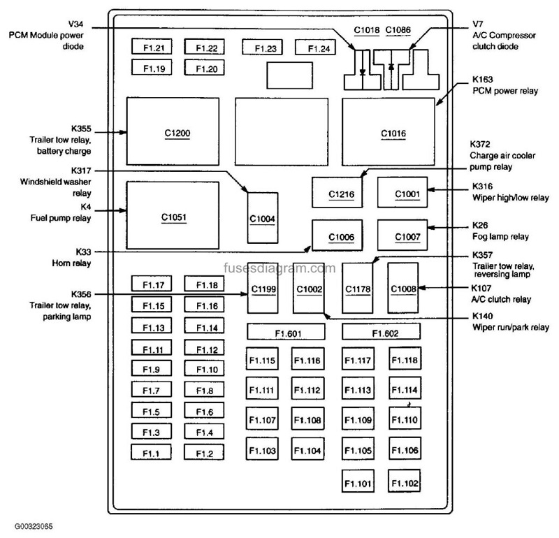
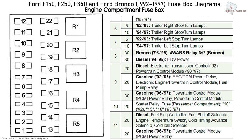
2004 Ford F150 Fuse Box Diagram
Fuses are an essential part of your truck’s electrical system. Not only do they prevent overheating, but they also help protect your wiring from damage caused by electrical overload. A fuse is a small device that stops a large electric current from flowing through it. It is different from a surge protector, which is designed to stop power surges. Most fuses are thin pieces of wire that allow only a small amount of current to pass. However, some are thicker, which allows more current to flow.
The electrical wiring in your 2004 Ford F150 is made up of a series of circuits. Each circuit has its own fuse. The fusebox is the place where you install the fuse. Older fuseboxes use bare pieces of wire between terminals. Newer fuseboxes use replaceable cartridge fuses. These have fuse wires built into a ceramic or glass cylinder, which can be snapped in and out. Fuses are less expensive than circuit breakers, but are more reliable for many applications. Fuses are also less likely to break, and they can be installed remotely or locally.
A blown fuse is an indication that your air conditioner is damaged or has a malfunction. When the fuse blows, the power will not come on again until you correct the problem. In some homes, panel breakers are installed instead of fuses. If you find that your AC is not working properly, it is best to seek professional help to replace it.
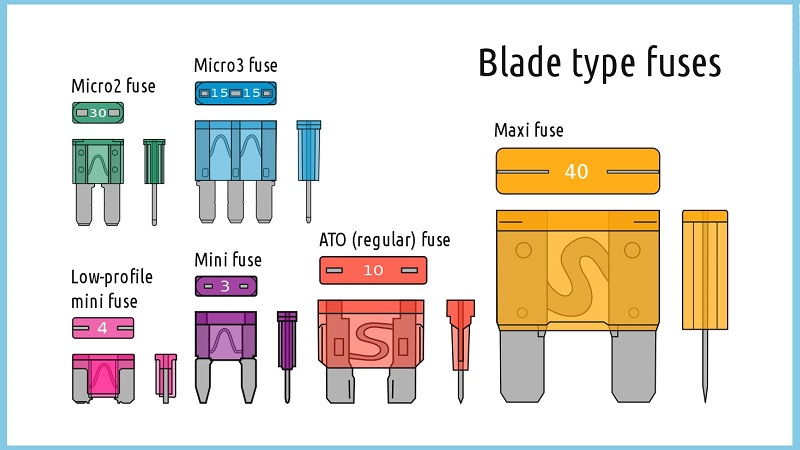
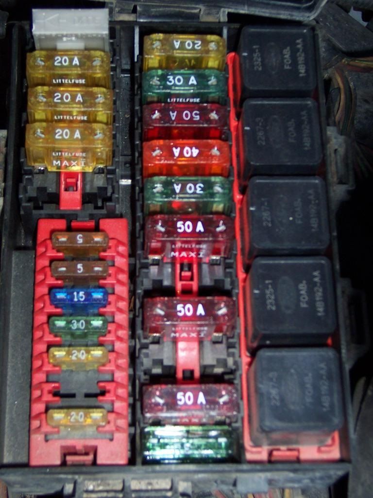
Blade fuses are used to denote amperage
There are several types of fuses in your 2004 Ford F150 Fuse Box Diagram. The most common are blade fuses, which come in various colors. The color of a fuse is a good indication of its amperage rating. The fuse will typically have the amperage number printed on its top. Make sure to purchase the correct sized fuse to prevent overheating. A fuse that is too small will repeatedly blow, and a fuse that is too large will cause your entire system to fail.
Fuse boxes can last the entire life of a vehicle. They also protect the electrical components in your vehicle from damage. The main function of a fuse is to prevent high voltage from affecting the drive switches. Fuse boxes also protect your vehicle against elements like water and weather. When a fuse blows, it will stop the car from functioning. It may also cause difficulty starting your vehicle.
Fuse replacement is an easy process, and it is also an important safety precaution. A blown fuse indicates an electrical problem, so it’s best to replace the fuse before replacing the rest of the electrical system. In the case of a blown fuse, it’s best to consult a professional for assistance.

2004 Ford F150 Fuse Box Diagram If you suspect a fuse is blown, look at the fuse box cover for a diagram. Take note of the fuse type and size. Blade fuses are categorized by amperage, and they’re color-coded to identify what amperage it can handle.

If you suspect an electrical problem, check the fuse first before visiting a mechanic. A blown fuse is a sign of an overloaded fuse and will need to be replaced.
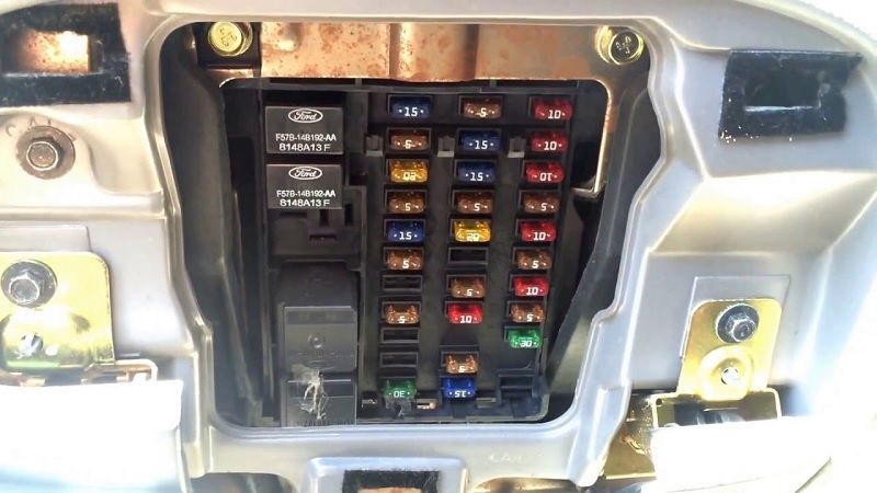
#2004 Ford F150 Fuse Box Diagram – Fuse panel is located under the instrument panel
The fuse box for your 2004 Ford F150 Fuse Box Diagram is located under the instrument panel. The fuse box is composed of several sections. These sections are located under the instrument panel and cover a range of electrical systems in your vehicle. These sections are arranged according to the system’s function.

The fuse box has several types of fuses. Some types are used for different purposes. You can find a list of all fuses by referring to the manual. There are some fuses that are specific to certain models. For example, you can find a 20A fuse for the intercooler pump in a supercharged engine, or a 30A fuse for the front blower on a regular engine. The fuse for these circuits can be replaced if necessary.

The fuse box is located on the right hand side of the instrument panel. 2004 Ford F150 Fuse Box Diagram Some of the fuses include the relay box located in the engine compartment on the left fender. The terminal assignments for these fuses are different depending on the model, equipment level, and market.

You can also find a 20A fuse that is used for the radio, PAD warning lamp, cluster airbag warning light, and PATS SecuriLock transceiver. The 20A fuse will power your trailer tow left stop/tail lights. A 25A fuse is also used for the 4.2L engine’s ignition coils. Besides these fuses, there are also five mini fuses that supply power to various other systems inside the vehicle.

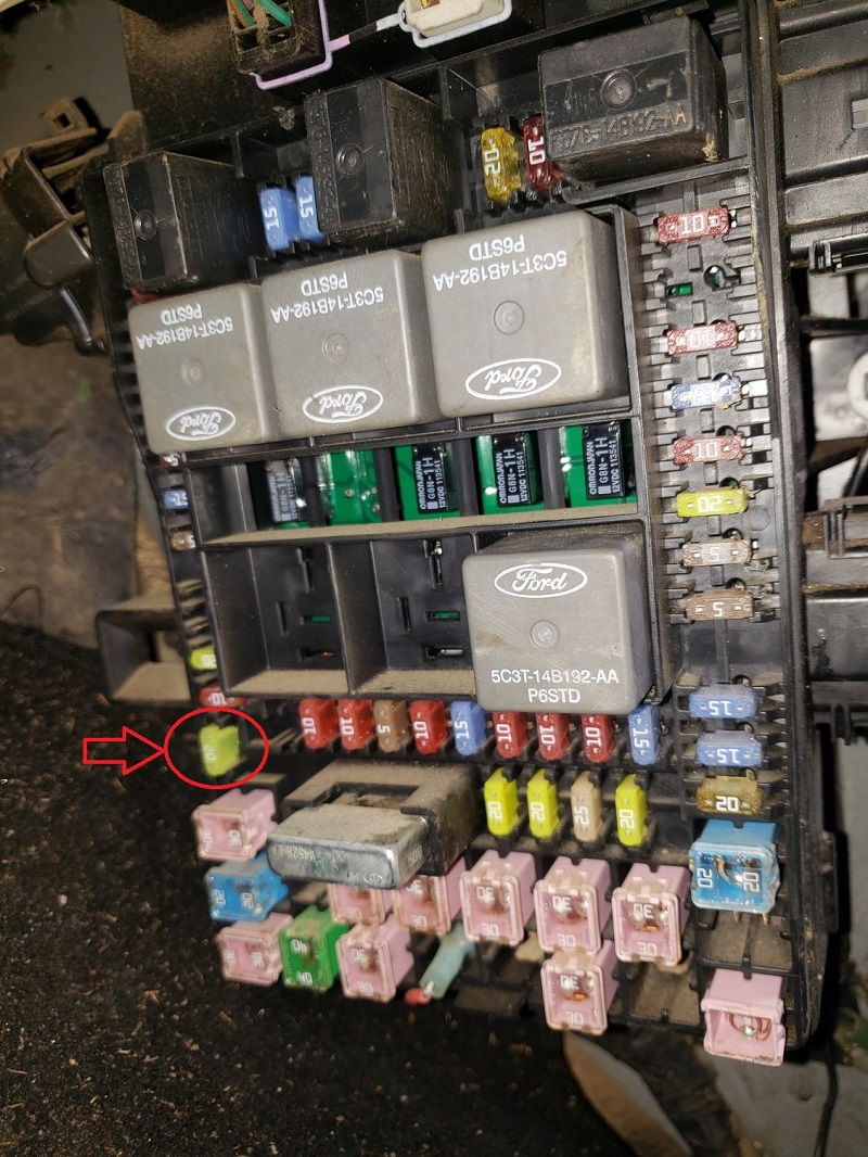
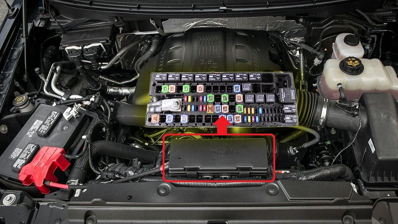
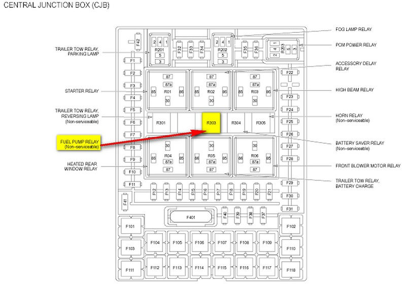
#2004 Ford F150 Fuse Box Diagram – Relay box is located in the engine compartment on the left fender
2004 Ford F150 Fuse Box Diagram The relay box is located in the engine compartment on the fender on the left side. To locate the relay box, remove the cover on the fuse box and the trim panel. Then, push the bottom of the cover until you hear a click. Finally, pull the cover to make sure it’s seated properly.
If you notice that the relay isn’t working, you can try to replace it. You can purchase a voltage tester that should cost around $15 or more. You can also buy a replacement relay from the aftermarket or OEM market. However, you need to remember that OEM parts are not always available and may be difficult to locate. If you are doing this repair yourself, make sure you understand the wiring diagram and engine controls before replacing the relay.

The 2004 Ford F150 Fuse Box Diagram has two different types of relays. The first type uses a four-pin charge while the other uses a five-pin charge. If the relay is not working, check the fuel pressure, the fuse, and the grounding strap to make sure everything is functioning correctly.

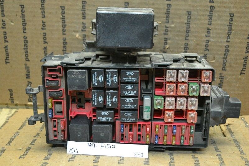
The fuse box is located underneath the right fender of the engine compartment. This white box contains fuses for various parts of the car. Check all the fuses to determine whether they’re blown or faulty. If the fuse is blown, you can replace it to restore proper operation of the components. If you are unsure of how to replace a fuse, you can always consult the owner’s manual, which is typically free to download.
| No. | A | Protected components |
| 1 | 10 | Run/Accessory – Wipers, Instrument cluster, Audio (’05-’08 – XL/STX) |
| 2 | 20 | Stop/Turn lamps, Brake on/off switch, Hazard flashers (’07), T/T electric brake module (’08), PCM (BOO signal (’08)), turn signal mirrors (’08), CHMSL (’08) |
| 3 | 5 | ’04-’05: Power mirrors, Memory logic power (’04), Memory seats and pedals |
| 7.5 | ’06-’08: Power mirrors, Memory seats and pedals, Driver power seat (’07) | |
| 4 | 10 | DVD battery power, Power fold mirror (’05-’08) |
| 5 | 7.5 | Keep alive memory for Powertrain Control Module (PCM) and climate control module |
| 6 | 15 | Parklamps, Body Security Module (BSM), Instrument panel illumination |
| 7 | 5 | Radio (start signal) |
| 8 | 10 | Heated mirrors, Switch indicator |
| 9 | 20 | ’06-’08: Fuel pump relay, Fuel injectors, Injector sense, Intake manifold runner control (4.2L) |
| 10 | 20 | Trailer tow back-up lamps relay, Trailer tow parklamp relay |
| 11 | 10 | A/C clutch, 4×4 solenoid |
| 12 | 5 | ’06-’08: PCM relay coil |
| 13 | 10 | Climate control module power, Flasher relay (’05-’08) |
| 14 | 10 | Back-up lamp and Daytime Running Lamps (DRL) relay coil, A/C pressure switch, Brake-shift interlock solenoid (’04), Heated PCV (5.4L), ABS (’05-’08), Trailer tow back-up lamps relay coil (’05-’07), Reverse park aid (’05-’07), EC mirror (’05-’07), Navigation radio (’07), Redundant speed control switch (’05-’08) |
| 15 | 5 | Overdrive cancel, Cluster, Brake-Shift Interlock (BSI (’04)) |
| 16 | 10 | ABS module (Run/Start power (’04)), Brake-shift interlock solenoid (’05-’08) |
| 17 | 15 | Fog lamp relay |
| 18 | 10 | Run/Start feed – Flasher relay (’04), Electrochromatic mirror, Heated seats, BSM, Compass, RSS (Reverse Sensing System), Power rail (’08), Run/Start feed – Overhead power point (’05-’07) |
| 19 | 10 | Restraints (Air bag module) |
| 20 | 15 | ’04: PCM 4×4 power |
| 10 | ’05-’07: Battery feed for overhead power point | |
| 10 | ’08: Power rail | |
| 21 | 15 | Cluster keep alive power |
| 22 | 10 | Delayed accessory power for audio, power door lock switch and moonroof switch illumination |
| 23 | 10 | RH low beam headlamp |
| 24 | 15 | Battery saver power for demand lamps, Flex fuel (’08) |
| 25 | 10 | LH low beam headlamp |
| 26 | 20 | Horn relay, Horn power |
| 27 | 5 | Passenger Air bag Deactivation (PAD) warning lamp, Cluster air bag warning lamp, Cluster RUN /START power (’04-’07) |
| 28 | 5 | SecuriLock transceiver (PATS), PCM IGN monitor (’06-’08) |
| 29 | 15 | PCM 4×4 power |
| 30 | 15 | ’05-’08: PCM 4×4 power |
| 31 | 20 | Radio power, Satellite radio module (’07-’08) |
| 32 | 15 | Vapor Management Valve (VMV), A/C clutch relay, Canister vent, Heated Exhaust Gas Oxygen (HEGO) sensors #11 and #21, CMCV, Mass Air Flow (MAF) sensor, Variable Cam Timing (VCT), Heated Positive Crankcase Ventilation (PCV) valve (4.2L engine), CID sensor (4.2L engine), 4.6L/4.2L EGR (’06-’08), Electronic fan clutch (4.6L/5.4L engines (’07)) |
| 33 | 15 | Shift solenoid, CMS #12 and #22, Ignition coils (’06-’08), 4.6L/4.2L EGR (’05) |
| 34 | 20 | Fuel injectors (’04-’05), PCM power, Intake Manifold Runner Control (4.2L engine) |
| 35 | 20 | Instrument cluster high beam indicator, High beam headlamps, DRL disable relay (’08) |
| 36 | 10 | Trailer tow right turn/stop lamps |
| 37 | 20 | Rear power point, Center console power point (’07) |
| 38 | 25 | Subwoofer power |
| 39 | 20 | ’04-’06: Instrument panel power point |
| 40 | 20 | Low beam headlamps, DRL |
| 41 | 20 | ’04-’06: Cigar lighter, Diagnostic connector power |
| 42 | 10 | Trailer tow left turn/stop lamps |
| 101 | 30 | Starter solenoid |
| 102 | 20 | Ignition switch feed |
| 103 | 20 | ABS valves |
| 104 | — | Not used |
| 105 | 30 | Electric trailer brakes |
| 106 | 30 | Trailer tow battery charge |
| 107 | 30 | Power door locks (BSM) |
| 108 | 30 | Passenger power seat |
| 109 | 30 | Driver power seat, Adjustable pedals, Memory module ((pedals, seats) (’07-’08)) |
| 110 | 20 | ’07-’08: Cigar lighter, Diagnostic connector power |
| 111 | 30 | 4×4 relays |
| 112 | 40 | ABS pump power |
| 113 | 30 | Wipers and washer pump |
| 114 | 40 | Heated backlite, Heated mirror power |
| 115 | 20 | ’08: Moonroof |
| 116 | 30 | Blower motor |
| 117 | 20 | ’07-’08: Instrument panel power point |
| 118 | 30 | Heated seats |
| 401 | 30 | Circuit breaker: Power windows, Moonroof (’04-’07), Power sliding backlite |
| Relay | ||
| R01 | Starter solenoid | |
| R02 | Accessory delay | |
| R03 | Hi-beam headlamps | |
| R04 | Heated backlite | |
| R05 | Trailer tow battery charge | |
| R06 | Blower motor | |
| R201 | Trailer tow park lamps | |
| R202 | Fog lamps | |
| R203 | PCM | |
| R301 | Trailer tow backup lamps (printed circuit board) | |
| R302 | – (printed circuit board) | |
| R303 | Fuel pump (printed circuit board) | |
| R304 | Battery saver (printed circuit board) | |
| R305 | Horn (printed circuit board) | |